The short answer: start with a maximum, finish with equal bays
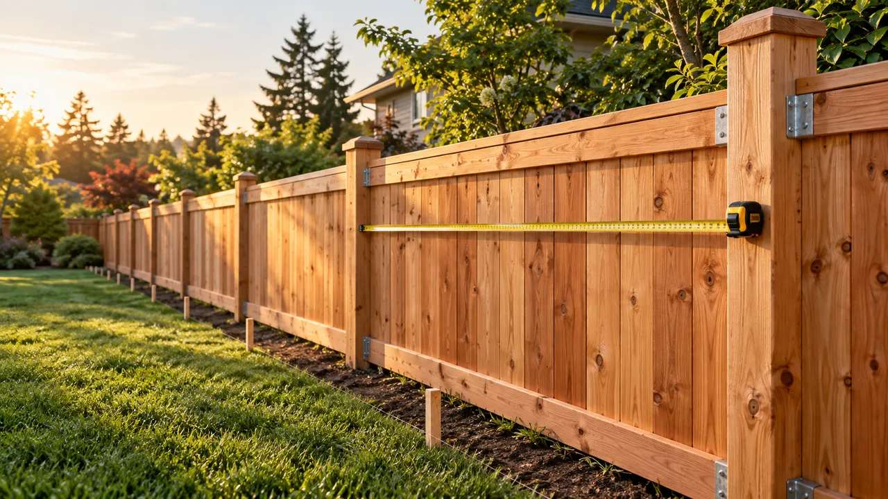
For many conventional residential wood fences, a designer begins with a maximum post spacing supplied by the plan, manufacturer, engineer, or local professional. Eight feet on center is a familiar planning input, but it is not a universal rule. A tall solid privacy fence catches far more wind than a low open picket fence. Heavy panels, weak soil, exposed coastal sites, frost movement, and gate loads can all require shorter bays, larger posts, deeper footings, or engineered details.
Once you have an approved maximum, do not simply mark that distance repeatedly and leave a short leftover panel at the end. Divide the run into a whole number of sections, then space the posts evenly. The basic method is:
- Measure one straight fence run.
- Divide the run length by the maximum allowed spacing.
- Round the number of sections up to the next whole number.
- Divide the run length by that section count to get equal actual spacing.
For example, a 50-foot open run with an 8-foot maximum needs ceil(50 ÷ 8) = 7 bays. Equal spacing is then 50 ÷ 7 = 7.14 feet, or about 7 feet 1¾ inches. An open run has one more post than bays, so it needs eight posts. The calculator below performs those steps, but you should still verify the selected maximum against the system you are building.
Measure each straight run separately
A reliable layout begins with endpoints, not panels. Confirm the property boundary and required setbacks before placing any stake. Locate underground utilities through the appropriate local service, identify easements, and check whether the municipality, homeowners association, or utility owner limits fence position or height. A beautifully spaced fence in the wrong place is still an expensive mistake.
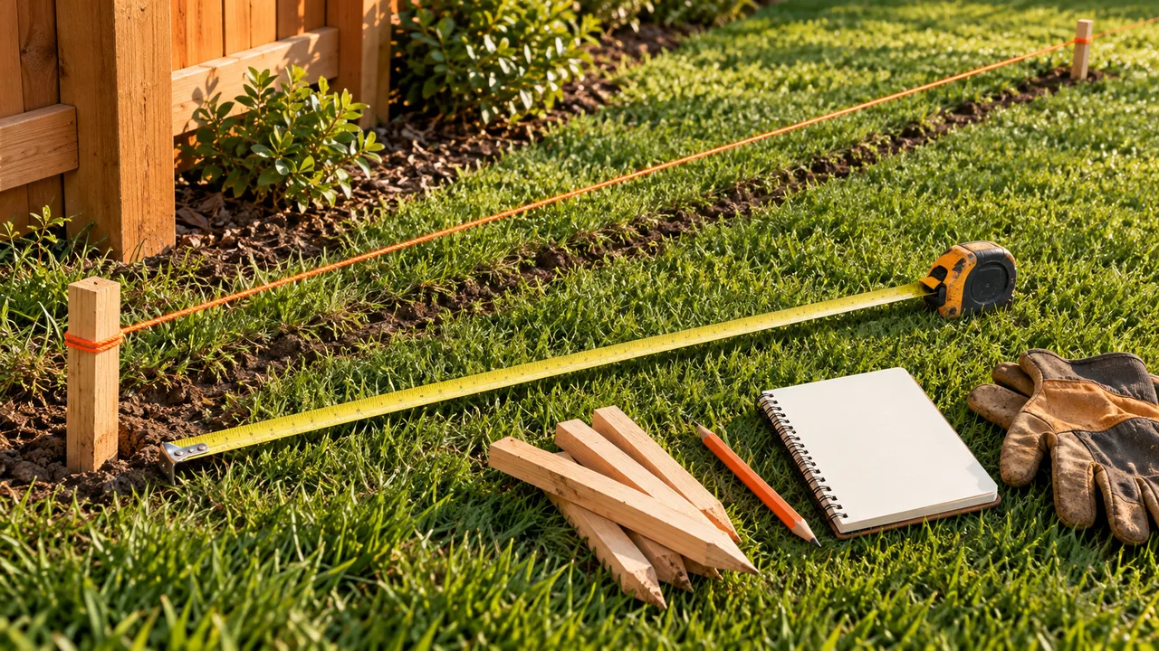
Set a stake at every end, corner, change of direction, and gate opening. Pull a mason line tightly between the endpoints of one straight run and measure along that line. Record every run as its own number. A U-shaped fence might be written as 36 feet, 62 feet, and 36 feet—not merely 134 feet—because each corner terminates a run and each run must be rounded independently.
Keep the measuring method consistent. Post spacing is normally discussed center to center. If you measure the clear distance between post faces but calculate as though it were center to center, the error repeats at every bay. On long lines, use a durable tape or a verified measuring wheel, keep it level where practical, and record obstacles such as tree roots, drains, retaining walls, or abrupt grade changes.
Before digging, compare the field measurement with the planned panel or rail system. Prefabricated panels may have strict opening dimensions, while site-built rails can often be trimmed. The more rigid the product, the more important it is to confirm actual component sizes before setting concrete.
Use the ceiling rule, then mark centers
The ceiling rule prevents any bay from exceeding the chosen maximum. Let L be the straight run length and S be maximum spacing. The number of bays is ceil(L ÷ S). Actual equal spacing is L ÷ bays. For an open run, posts equal bays plus one. For a truly closed perimeter, the last post is also the first, so the number of unique posts equals the number of bays.
Consider a 73-foot run with an 8-foot maximum. Dividing gives 9.125. Rounding down to nine would create 8.11-foot bays, which exceeds the maximum. Rounding up gives ten bays at 7.3 feet each. That small reduction produces a symmetrical result and respects the design limit.
To transfer the answer to the ground, hook the tape at the center of the first terminal post and mark cumulative centers: 7.3, 14.6, 21.9 feet, and so on. A second method is to mark the first and last centers, stretch a line, then use a story pole cut to the calculated interval. Recheck the final mark before drilling. Small rounding differences should be distributed rather than hidden in one noticeably narrow bay.
Measurements in feet often need conversion to feet and inches. Multiply the decimal remainder by 12. In the 7.3-foot example, 0.3 × 12 = 3.6 inches, so the spacing is about 7 feet 3⅝ inches. Choose a practical rounding precision that your tools can reproduce, then verify the accumulated endpoint rather than trusting dozens of individually rounded marks.
Fence design, wind, soil, and structure can change the limit
A spacing calculator answers an arithmetic question; it does not design the structure. Solid boards behave like a sail, while open pickets and chain-link allow more air through. Increasing fence height increases leverage on the post and footing. A lightweight decorative boundary and an eight-foot privacy screen should not inherit the same assumptions merely because both are called fences.
Material systems also behave differently. Site-built wood rails can be selected and cut to suit a layout, but a vinyl or composite panel may require exact openings and specific steel reinforcement. Chain-link fabric uses line posts and stronger terminal posts at ends, corners, and gates. Always read the current installation instructions for the exact product, including allowable post spacing, rail spans, wind ratings, and hardware.
Ground conditions matter. Loose fill, expansive clay, saturated soil, shallow bedrock, and frost-susceptible ground can change post and footing requirements. So can an exposed hilltop, hurricane-prone region, pool barrier, retaining condition, or fence carrying screens and planters. If the fence is safety-critical, unusually tall, heavily loaded, or governed by a permit, obtain local professional guidance.
Shorter spacing is not automatically a complete solution. More posts may reduce rail span, but undersized posts, inadequate embedment, weak concrete, poor drainage, or inappropriate fasteners can still lead to failure. Think of spacing as one connected design variable. Confirm it alongside post size, post material, hole diameter, embedment depth, rail size, fastener schedule, and bracing.
Count end, corner, and gate posts before line posts
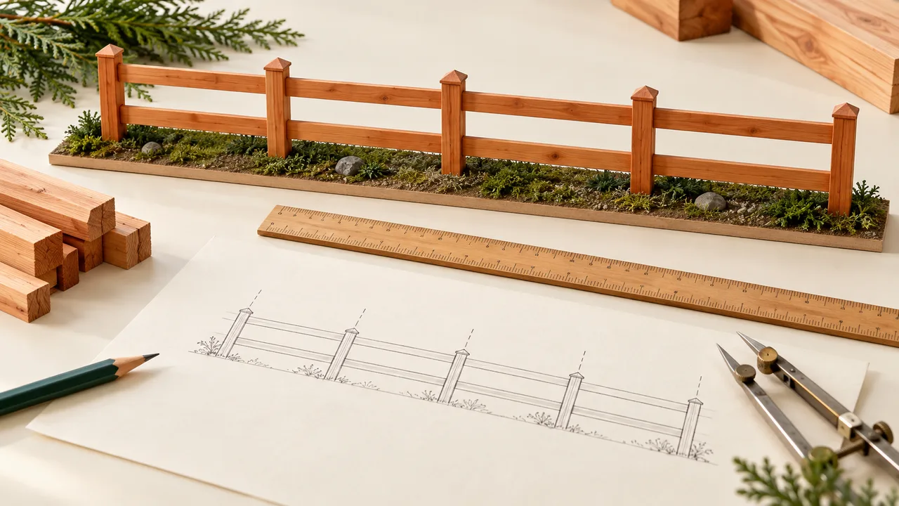
Not every post performs the same job. End posts terminate a line. Corner posts resist loads from two directions. Gate posts carry moving weight and repeated impacts. In chain-link terminology, these are commonly grouped as terminal posts and are typically larger or more heavily founded than intermediate line posts. Wood and vinyl systems likewise require special gate and corner details even if the vocabulary differs.
Lay out these structural points first. A simple open run has two terminal posts. An L-shaped layout has two ends and one corner. A gate opening normally has a post on each side, but do not blindly add two if one side coincides with an existing corner or end; count unique physical posts from the drawing. Double gates may require especially robust posts, drop rods, stops, and clear swing space.
Gate width is another source of confusion. The named gate size may describe the nominal leaf, the rough opening, or the passage width, depending on the manufacturer. Hardware needs clearance for hinges and latches. Obtain the gate instructions before concrete is placed, and measure between the correct post faces. A small mistake here can prevent a prefabricated gate from fitting.
After terminal and gate centers are fixed, calculate each remaining segment separately. If a 40-foot line contains a four-foot gate, it is not always correct to treat the remaining 36 feet as one run. The gate divides the line into two independent segments, each with its own endpoints and rounded number of bays. A dimensioned sketch prevents double counting and makes the material list auditable.
Handle slopes, steps, and direction changes deliberately
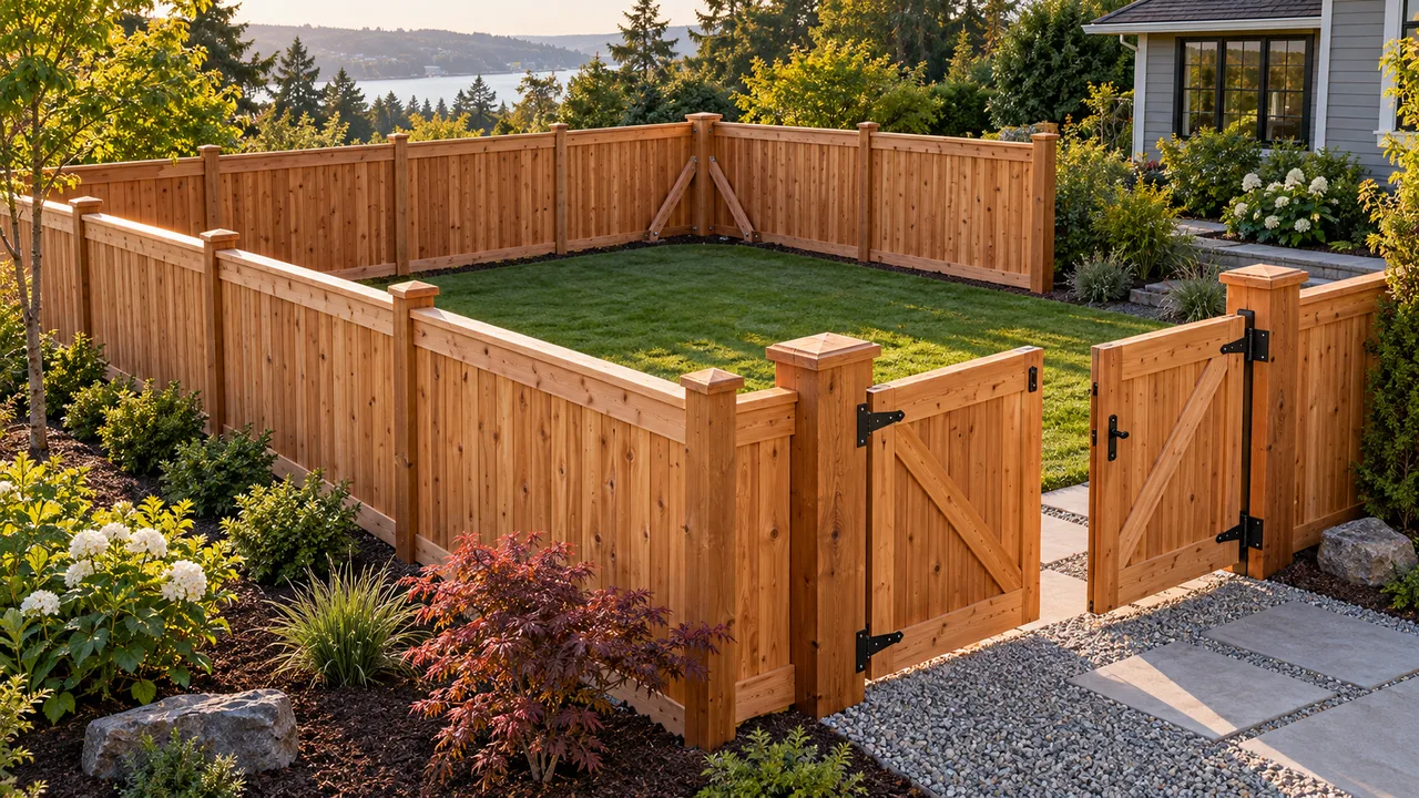
On sloping ground, decide whether the fence will rack with the grade or step in level panels. A racked fence keeps its top and bottom generally parallel to the slope; a stepped fence keeps each panel level and changes height at posts. Product geometry, appearance, ground clearance, privacy, pet containment, and installation instructions influence the choice.
Measure a sloped run using the method required by the system. A plan-view horizontal distance and a tape laid directly on the slope are not identical. Prefabricated panels often have limited racking capability, and their actual post-to-post opening may control the layout. For steep or irregular ground, a measured site drawing with elevation points is more useful than a single total length.
Stepped panels make post placement visually prominent. Equal horizontal bays may still create uneven steps if the grade changes abruptly. Break the run at intentional transition points, then calculate each segment. Avoid placing a post directly in an unstable edge, drainage swale, buried service route, or where excavation could undermine a retaining structure.
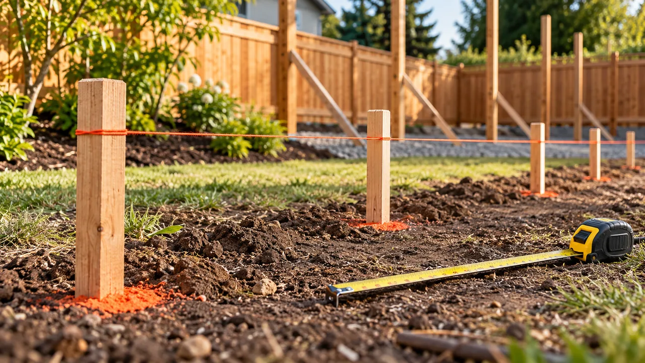
Use a taut line for alignment, but do not let it hide grade variation. Establish both the fence-line center and the planned top profile. Temporary batter boards or offset strings can remain in place while holes are dug. Recheck plumb, center-to-center distance, post height, and alignment before concrete hardens. The calculator can distribute bays; only careful field layout can make them straight and visually calm.
Worked layout example and final checklist
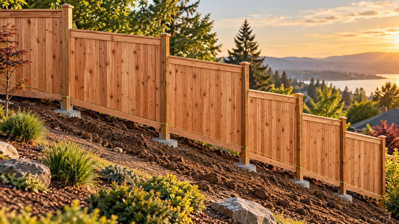
Imagine a three-sided backyard fence with straight runs of 28, 51, and 28 feet, plus one four-foot gate in the middle of the long side. Suppose the approved maximum spacing is 8 feet. Each 28-foot side needs ceil(28 ÷ 8) = 4 bays, so its equal spacing is 7 feet. The long side must be split at the gate. If the gate is centered, each remaining segment is 23.5 feet. Each segment needs three bays at about 7.83 feet.
Draw the unique posts before totaling. There are two outer end posts, two corner posts, and two gate posts. The first side has three intermediate line posts between its end and corner. Each half of the long side has two intermediate line posts between corner and gate. The final side has three intermediate posts. The drawing therefore shows six structural endpoint/corner/gate posts and ten line posts, for sixteen unique posts. This visual count is safer than adding independent run totals and accidentally counting shared corners twice.
Before ordering or digging, complete this check:
- Boundary, setbacks, easements, permits, and utility locates are confirmed.
- The product instructions or approved design provides the maximum spacing.
- Every end, corner, direction change, and gate post is marked.
- Gate rough openings match the chosen hardware.
- Each straight segment is calculated and its marks are measured from one reference.
- Post size, embedment, hole diameter, drainage, concrete, rails, and fasteners suit the complete system.
- The final marks have been checked for alignment, equal appearance, and conflicts.
Once the layout is stable, move to the full Fence Material Calculator to estimate posts, rails, pickets, concrete bags, waste, and optional unit costs. Keep your field sketch with the result so every number can be traced back to a real run.